Tips for Choosing the Right Toolholder for High-Speed Machining
Appears in Print as: 'High-Speed Toolholder Considerations'
Here is some advice for shops hoping to maximize their efficiency performing high-speed milling operations.
#techbrief
Edited by Derek Korn

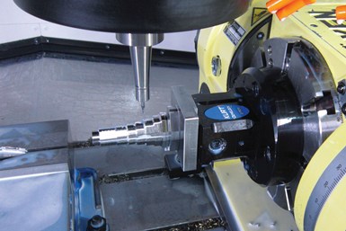
Choosing the proper toolholder is an important element of devising an effective high-speed machining process. (Photo credit: PM)
High-speed machining gained popularity in the 1990s, especially in the aerospace industry which replaced fabricating processes with machining monolithic parts such as wing struts from billets of material. Machine tools capable of spinning cutting tools at tens of thousands of rpm made it easier to produce these parts faster.
Like those machines, toolholders adapted. The centrifugal forces they had to manage to keep tools cutting correctly became extreme. The toolholding systems available at that time were found not to be as effective as the shallower 1-to-10 taper ratio of the hollow taper shank, or hohl shaft kegel (HSK) in German. The HSK has since been standardized to ISO specifications (12164-1, -2).
Featured Content
HSK is now available in several sizes and forms to fit with small-to-large machines. For the most part, the market has settled on form A for general milling. It has been adopted in Japan, North America and Europe and is one of the only worldwide toolholder standards. Form E or F are more geared toward high-speed machining applications.
Regardless, to achieve efficient tool life, proper finish and productivity in high-speed machining, toolholders must be as rigid, compact and short as possible to keep the entire assembly stable. Here are eight key points to consider when choosing a high-speed toolholder:
- Use OD/nuts with as few holes or slots as possible reduce noise, coolant splatter and enhance strength.
- Extra contact length of the internal taper of chuck bodies strengthens grip.
- Collet overhang should be limited.
- For the spindle interface, Big Daishowa recommends licensed dual-contact toolholders for maximum stability.
- The higher the gripping force the better.
- A shallow collet taper and micro-mirror, ground-finished surfaces improve concentricity and balance.
- Collet nuts must be tightened safely for secure clamping and pull stud protection.
- Consult ISO 16084 provisions for the definition of maximum imbalance for different applications, defined as “standard or roughing operations” and “fine or finish operations.”
Remember Toolholder Balancing
When it comes to balancing toolholders, the quality G2.5 is widely used in the industry and is described in the ISO 1940-1 standard issued in 2003. However, this quality class is often over-specified and is in many cases not economically or technically feasible, especially when applied to smaller and lighter tools. Standards often applied to tools are more suited for rigid rotors and are practical in a broader use for balancing.

ISO 16084 focuses on the interaction between spindle and tool factoring in the allowable load on the spindle bearings generated by a tool’s imbalance. This load must not exceed 1% of the dynamic load capacity of the spindle bearings. (Photo credit: Big Daishowa)
However, it cannot be applied to a complete system of spindles, toolholders and tools adequately and within technical constraints. For example, for a tool to be compliant, it will have to be balanced to less than 1 gmm/kg at a speed of 25,000 rpm, which in turn corresponds to a mass eccentricity of less than 1 micron. This allowable tolerance is less than the interchange accuracy for even HSK, essentially negating all the costs and time for balancing the tool to such a strict tolerance.
For this reason, all Big Daishowa toolholders are balanced according to ISO 16084 (issued in 2017), which was specifically developed for rotating tool systems. ISO 16084 focuses on the interaction between spindle and tool factoring in the allowable load on the spindle bearings generated by the tool’s imbalance. This load must not exceed 1% of the dynamic load capacity of the spindle bearings.
According to ISO 16084, the allowable unbalance tolerance is specified in (gmm) and is not expressed using a special quality grade (G). Big Daishowa does not indicate any G values for balancing quality, but rather the maximum rotational speeds of the individual tool holder.
The company’s Mega holder program includes a variety of styles that can be used as high as 40,000 rpm. According to the company, it guarantees 100% concentricity and runout accuracy as low as 0.00004 inch at the nose and says this system is built specifically to withstand speed and forces required in a high-throughput environment.
RELATED CONTENT
-
A Guide to Insert Coating Processes and Materials
Few materials have had a greater impact on our economy and industrialized culture than cemented tungsten carbide.
-
Calculating Surface Footage and RPM for Optimum Tool Life
Tech Brief: Calculating Surface Footage and RPM for Optimum Tool Life
-
Skiving Long, Slender Parts with Tight Tolerances
Here's a look at one of the oldest and most efficient methods of screw machine production for parts that are long and slender, with close-diameter tolerances and finishes, or parts that require truly spherical radii.


