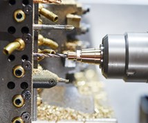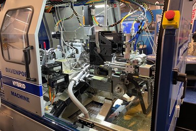
Introduced in 2017, the Hybrid multi-spindle machine combines CNC and cam-driven functionality for precision part production in high volumes.
“These are two questions we commonly receive about our Hybrid multi-spindle platform,” says Dan Bavineau, chief manufacturing and technology officer for Davenport Machine (part of Brinkman International Group Inc.).
The Hybrid concept, which represents the next evolution of the company’s heritage five-spindle, multi-spindle screw machine, combines CNC technology with some familiar cam-driven functionality which Bavineau says enables these machines to realize fast cycle times while offering tighter process control and precision. He notes it was also engineered to offer intuitive programming and increased flexibility at an affordable price point for a high-production, multi-spindle offering.
Featured Content
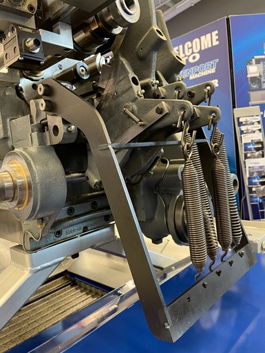
To reduce machine cost, cams are still used to control the motion of the machine’s four end-working spindles commonly used for basic drilling and tapping in which the tools simply feed in and out of the part.
A number of design improvements and additions have been made since this machine’s introduction in 2017. You can read about those at gbm.media/thehybrid. But, the company still fields questions about what elements of the machine remain cam driven and for what reasons.
As Bavineau explains, cams are still used to control the motion of the machine’s four end-working spindles commonly used to drill, tap or slot. To give the CNC functionality would require additional components such as ballscrews, encoders, servomotors and electronics that would greatly add to the machine’s overall cost. Plus, the majority of end-working operations require simple motion — feeding in and feeding out — that can easily and repeatably be handled via cams. Still, these spindles are independently driven and can rotate at different speeds to optimize each end-working process.
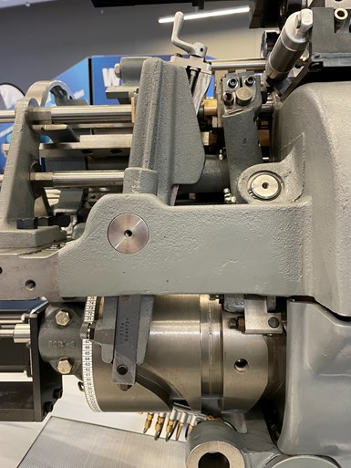
A drum cam is used to maintain overall cycle synchronization.
In addition, the entire machine cycle runs off of a drum cam which is used to maintain overall cycle synchronization. For example, it is used to index the machine’s revolving head and drive the cam bank that moves the end-working spindles.
But, while there are minimal cam-driven functions in the Hybrid design, the concept of “cams” can be a concern for some, Bavineau admits. This is one reason why Davenport has developed its Layout Assist Module. This software walks users through their machining sequence by entering values such as speeds and feeds for all operations to calculate overall part cycle time. In addition, it automatically determines cam geometry and timing, enabling Davenport to design and manufacture cams for shops. Therefore, shops no longer need personnel with vast multi-spindle experience to create their own cams. Bavineau says this is a way to turn multi-spindle machining into more of a science and less of an art that would otherwise require a wealth of in-house multi-spindle tribal knowledge. Most cams ship within 24 hours after placing an order.
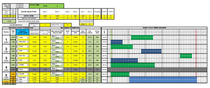
Davenport’s Layout Assist Module calculates overall part cycle time for users while automatically creating cam geometry. The company can then manufacture and ship the cams to users. Photo Credit: Davenport Machine
And, to further engage the industry, the company in February began offering free, weeklong training classes for both traditional heritage Davenports and the Hybrid platform at its Rochester, New York, headquarters and manufacturing campus. Those who participate pay only for transportation and lodging.
RELATED CONTENT
-
Turning to an Adhesive for Lathe Workholding
Adhesive cured by ultraviolet light is an option for securing parts for machining that could otherwise distort when traditional, mechanical clamping techniques are used.
-
The Evolution of the Y Axis on Turn-Mill Machines
Introduced to the turn-mill machine tool design in about 1996, the Y axis was first used on a single-spindle, mill-turn lathe with a subspindle. The idea of a Y axis on a CNC originated from the quality limitation of polar interpolation and the difficulty in programming, not from electronic advances in controls or servomotor technology as one might commonly think.
-
A New Approach to CNC Turning
This turning process takes advantage of a turn-mill’s B-axis spindle to vary a tool’s approach angle to optimize chip control and feed rates.


