Understanding Micro-Milling Machine Technology
Micro-milling can be a companion process to turning-based production machining. This article looks at some of the technologies that go into a micro-milling machine and why they are important to successful operation.
#micromachining #basics
Technology transitions, along with moving outside your comfort zone, can be rather painful, particularly in the manufacturing sector. Management, engineering and the movers and doers out on the shop floor don’t always see eye to eye regarding any new technology that gets introduced into the company.
But in today’s highly competitive production market, change is inevitable in order to survive. What you are doing today and how you are doing it will not be the same in 5 to 10 years. However, it’s not about creating an immediate paradigm shift for tomorrow’s work, but rather subtle changes into new technology and new markets over time.
Featured Content
One such technology that complements Swiss-type production machining is micro-milling. Micro-milling has traditionally held its roots in the European market, but throughout the last few years it has been rapidly expanding into the U.S. market. For those already embracing small part production on Swiss-type machines, micro-milling is a developing market that can provide competitive leadership compared to those with little or no experience working with small parts.
Unfortunately, machine technology for micro-milling is different. Further, it goes beyond the boundaries of traditional milling equipment and, like any technology, it can be a jungle out there. In order to take the first steps into micro-milling, it’s important to unravel some of the machine technology behind the equipment as well as the supporting technology that goes with it.
Circle of Technology
The success of any company is highly dependent upon each individual department. If one department is not running at 100 percent, it has the potential of affecting the whole company. The affecting potential is dependent on the business model of the company and what it produces.
Likewise, a machine is made up of individual components. If one component is not at 100 percent, the machine may fail at producing a quality part. How the machine is used and what it’s producing will naturally determine the affecting potential on the part.
However, unlike traditional milling, which is less forgiving, micro-milling requires a tighter quality relationship within every machine component. In other words, if there is a slight quality issue with the spindle, chances are it will have a negative effect on the part quality and may result in total failure. For micro-milling, each component is critical in the success of producing a good micro-machined part.
Machine Construction
and Geometry
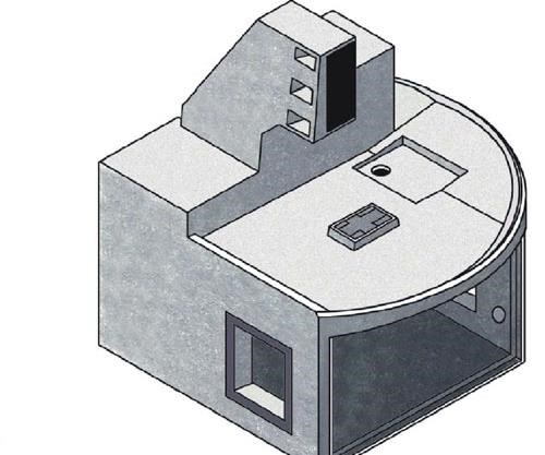
Machine geometry plays an important role on the overall performance of the machine. It will determine the stiffness, accuracy, thermal stability, damping properties, work volume and ease of operator use. The two most popular vertical machine geometry types are bridge and C-frame construction, each offering various pros and cons.
However, a C-frame construction typically offers the best stiffness for micro-machining since stiffness directly affects accuracy. In a C-frame design, the only moving axis is the spindle or the Z axis, thus there is less weight offering better dynamic stiffness.
Stiffness decreases in C-frames as the length of Z travel increases. The ideal C-frame construction is one that has a suitable balance between the design intent and the length of Z travel. With a bridge construction, both the X axis and the Z axis are suspended above the X-axis table. The bridge therefore carries a greater amount of weight offering less dynamic stiffness for micro-milling. Most bridge constructions are better suited for high-speed machining of medium to larger parts where maximum Z travel is commonly required.
One of the more devastating machining attributes of milling small, delicate and accurate parts is vibration. Like stiffness, damping is a critical element that needs to be under control during micro-milling. Machine tools with increased damping will absorb more of the vibrations induced by cutting. Many machines’ frames are constructed using cast iron or steel weldments.
Unfortunately, these types of structural materials are not suitable for micro-milling. The most suitable machine frame material for micro-milling is polymer concrete. Polymer concrete often provides as much as 10 times higher absorption of vibrations than cast iron. Polymer concrete also provides superior dynamic and static rigidity than cast iron and has substantially better thermal stability properties, which are crucial for achieving small-part accuracy.
Guideway System
The machine tool way system includes the load-bearing components that support the spindle and table, as well as guiding their movement. There are two primary guideway systems: box ways (sometimes called hydrodynamic ways) and linear guides. Each system has its positive and negative characteristics.
Unfortunately, one type of way system is not appropriate for all applications. Box ways are used on a large percentage of machines and are most commonly found on large metal removal machining centers. Because of their design, box ways are problematic where frequent axis reversals are required and low friction motion is needed for extreme accuracy. A linear guideway system is the choice for a micro-milling machine. They offer low static and dynamic friction and are well suited for a high degree of multi-axis and complex motion.
Drive and Motion Technology
How small of a part a shop can machine and how successful a shop is depends on the drive and motion technology built into that shop’s micro-machine. There are several types of drive and motion technology on the market today. However, ballscrew technology is still the driving force behind the axis drive mechanism on most machine tools.
Ballscrews are driven by servomotors. This combined technology of ballscrew and servomotor still remains suitable for micro-milling machines. Technology such as linear motors do not provide significant advances compared with traditional ballscrew technology for micro-milling. What does remain important is how the drive and servomotors work together to provide precise and accurate motion in order to produce miniature-size 3D features. Feedback devices, such as glass scales and motor encoders, are placed on machine tools to determine position.
Many machine tool manufacturers only use rotary encodes to determine actual position of an axis. However, rotary encoders only determine distance travel or the speed of travel and do not account for backlash, wear or thermal changes with the ballscrew. Any of these geometrical changes with the ballscrew will cause errors in the actual position. To counteract these geometrical changes and to ensure the most precise axis position, glass scales are placed close to the guideways to provide additional feedback to the control.
Glass scales come in a range of precision, but most precision high-end machine tools commonly use a 0.5-micron increment in conjunction with the rotary encoder. Since many applications in micro-milling are small and detailed—requiring the smallest incremental motion, 0.5 micron glass scales may not be significant for producing small, ultra-precision parts. In this case, 0.1 micron glass scales are available to produce even the most detailed micro-machined parts.
Spindle
Spindle technology has come a long way through recent years. There are many types of spindles on the market: gear driven, belt driven, motorized, air driven and hydrostatic. The more common high-rpm spindles are motorized spindles. A motorized 160K-rpm spindle was unheard of only a few years ago. Although a 160K spindle has its applications, the more common high-speed spindles are more applicable to have an rpm of as high as 50K.
With micro-milling, tool size is relative to the application. Commonly, a 6-mm-diameter tool would be considered large and a 0.3-mm-diameter tool would be considered quite small. In this range, a spindle of 50K rpm would provide an adequate solution.
Motorized spindles come in two basic forms: open loop or closed loop. A closed loop spindle is commonly called a vector spindle. Open loop spindles are generally used when cutting forces are relatively small such as in micro-milling. They are also less expensive, but have a number of drawbacks. Open loop spindles have no encoder feedback.
Therefore, operations such as rigid tapping and spindle orientation are not supported. Further, the ratio between minimum and maximum spindle speed is limited. For example, an open loop spindle of as high as 40K rpm may have a low-end rpm of only 2K. A spindle less than 2K rpm does not develop enough torque for cutting.
The ideal spindle for micro-milling is a closed loop or vector controlled spindle. They offer the range of rpm, full torque at low speeds, rigid tapping capabilities and spindle orientation. A well-designed vector control spindle on a micro-milling machine will offer a large amount of flexibility along with the abilities of cutting even the most difficult-to-cut materials.
Toolholder and Spindle Interface
The toolholder and spindle interface is the design configuration between the spindle and the toolholder. There are a number of different toolholder interfaces for milling. Some of the more common ones are called steep tapered toolholders such as CAT, BT and ISO. These are used on the majority of milling machines and come in various sizes. Another type of interface is called HSK. HSK tooling has rapidly been adopted for high-speed spindles and for use on high precision machining centers.
Tapered toolholders establish their axial position in the spindle through the mating of two tapers. One of the disadvantages of this interface is that as spindle speeds increase, the spindle shaft tends to expand because of centrifugal force and thermal effects. When this occurs, the taper of the toolholder can be drawn further into the spindle thus causing a number of problems including inaccuracies in Z-axis motion.
Because micro-milling uses high rpm, tapered toolholders are not the ideal toolholder type. HSK toolholders offer a number of advantages for high rpm spindles and thus are the preferred choice for micro-milling machines. HSK toolholders are retained in the spindle by a set of internal grippers located inside the spindle.
As rotational speeds are increased, metal-to-metal contact between the toolholder and the spindle is maintained because centrifugal forces cause the internal grippers to expand within the toolholder, pressing it firmly against the inside of the spindle shaft. HSK tooling is also a double-contact interface. It locates on both a shallow taper and a flange, creating a rigid precision fit for both axial and radial cutting forces.
This precision fit allows the interface to have superior runout conditions compared to steep tapered tooling. When working with very small cutters, runout inaccuracies can cause premature cutter failure. Further, excessive runout can also reduce the life expectancy of the spindle. For micro-milling machines, the ideal runout inaccuracy should be 1 micron or less.
CNC Technology
Control technology is another area on the machine tool that has seen advances. Thanks to advanced hardware and software technology, today’s CNC controls are fast and powerful. Unfortunately, the topic of CNC control technology is complex. Books have been written on the topic alone.
However, there are a number of important aspects regarding control technology that can be pointed out here—control interface, motion control and feedback, processing speed and support. A control interface doesn’t seem like a logical problem, but high-tech machine tools require high-tech controls and most high-tech controls are packed with numerous features.
These features can be quite overwhelming to an end user, thus creating an intimidating work environment. The interface should be logically laid out and simple to use, yet flexible enough to handle even the most complex toolpaths’ output from any CAD/CAM system.
Because micro-milling tool paths can be complex, containing thousands of blocks of information, it’s important that the control is able to accept several types of storage media along with an Ethernet connection. Motion control and feedback are crucial for precision micro-milling applications. The control must be able to process high density complex data fast and be able to command the motion to the axis in a precise manner.
How fast the control is able to do this will depend on a number of internal factors that are beyond the scope of this text. The best solution is to select a micro-milling machine with proven control technology from a respected and well-known company. In this case, support will become a natural spin-off providing years of excellent support.
Auxiliary Components
Working with small parts and tools can be frustrating at times. During milling, cutting tools need to be measured for both length and diameter size. This information is fed back to the control to make offset compensations for the tool path.
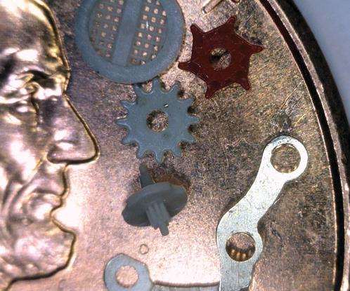
Measuring tools that can hardly be seen by the human eye are almost impossible to measure mechanically. Many machine tools are using laser measuring devices to automatically measure both the tool’s length and diameter using a small laser beam of light. With an adequate laser measuring system, tools as small as 40 microns are able to be measured in a reliable and easy manner.
Small parts and fixtures can also be challenging to set up. The use of a touch probe can make setting up a micro-milling machine much easier. Automatic centering, part zeroing and part alignment can be used to quickly establish part orientation. Additionally, part measuring can also be done using many of the touch probe routines that are commonly found on controls that feature probing.
Completing the Circle
A good micro-milling machine alone will not guarantee success at micro-part manufacturing. Work environment including a temperature control work area, cleanliness and organization are all important areas that need attention during a transition toward micro-milling. Further, working with tools as small as 50 microns takes a bit of knowledge and a great deal of experience. Be sure the machine tool builder has knowledge and experience to fully support you and guide you towards successful micro-milling.
RELATED CONTENT
-
German Project Yields Three New Medical Machining Processes
Recent research has resulted in a new mix of high-speed turn whirl milling, polygon turning and rotational turning for manufacturing medical bone screws and out-of-round nails.
-
Tips for Choosing the Right Toolholder for High-Speed Machining
Here is some advice for shops hoping to maximize their efficiency performing high-speed milling operations.
-
Video Tech Brief: Live-Tool, Y-Axis CNC Lathe with a Compact Footprint
This small footprint, big-bore lathe offers a generous work envelope. The addition of Y-axis and live tooling enables milling, drilling and tapping for increased machine capabilities.


