A Close Look at Indexable Chucks
It's not for every application but when the right one comes along, these chucks can help work wonders.
Workholding is not usually thought of as a profit center, but increasing the number of turning operations per chucking that can be performed on a workpiece can have a ripple effect throughout your operation—one that extends all the way to your bottom line. That is precisely what indexing chucks are designed to do.
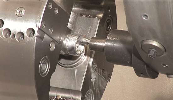
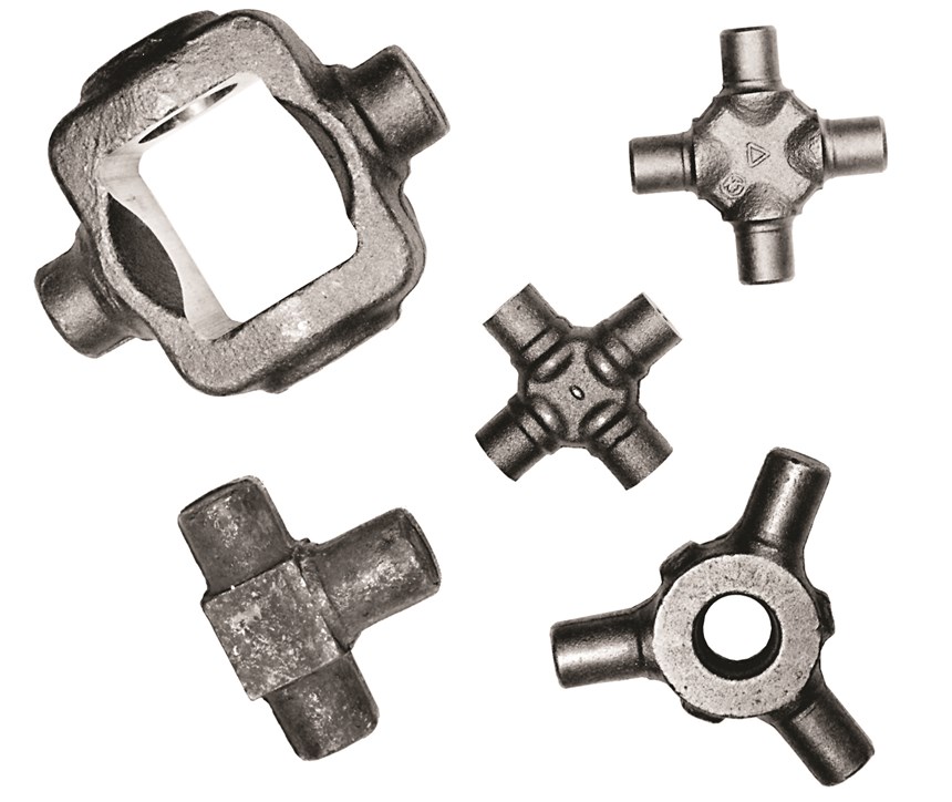
Indexable chucks are intended primarily for parts with intersecting axes, such as universal joint spiders, couplings, valve bodies and trunnions, which require multiple turning operations. Indexable chucks sequentially present the different sides or faces of these parts to a turning tool for machining when prompted by M-codes in the workpiece’s CNC program. Thus, it is possible to perform all the necessary turning operations in one setup. This simple fact not only shortens cycle time and boosts productivity when processing parts with intersecting axes, but can also enhance a shop’s operational efficiency in a number of other ways as well. First, however, is a description of how they operate.
Featured Content
The motion of these chucks can be divided into two categories, indexing and clamping, both of which are hydraulically actuated by cylinders within the chuck. The hydraulic oil is fed to the cylinders by an oil supply system mounted on the spindle end in conjunction with a pipe bundle running through the spindle bore.
Note that with older style semi-automatic indexing chucks, the indexing is hydraulically actuated, but the clamping is done manually with a wrench. However, the semi-automatic indexing chuck, while cheaper than the automatic type, also results in a smaller productivity increase, thus weakening one of the advantages of indexing chucks. For this reason, the semi-automatic indexing chuck is a vanishing breed, one that is most likely to be encountered only in a handful of legacy applications.
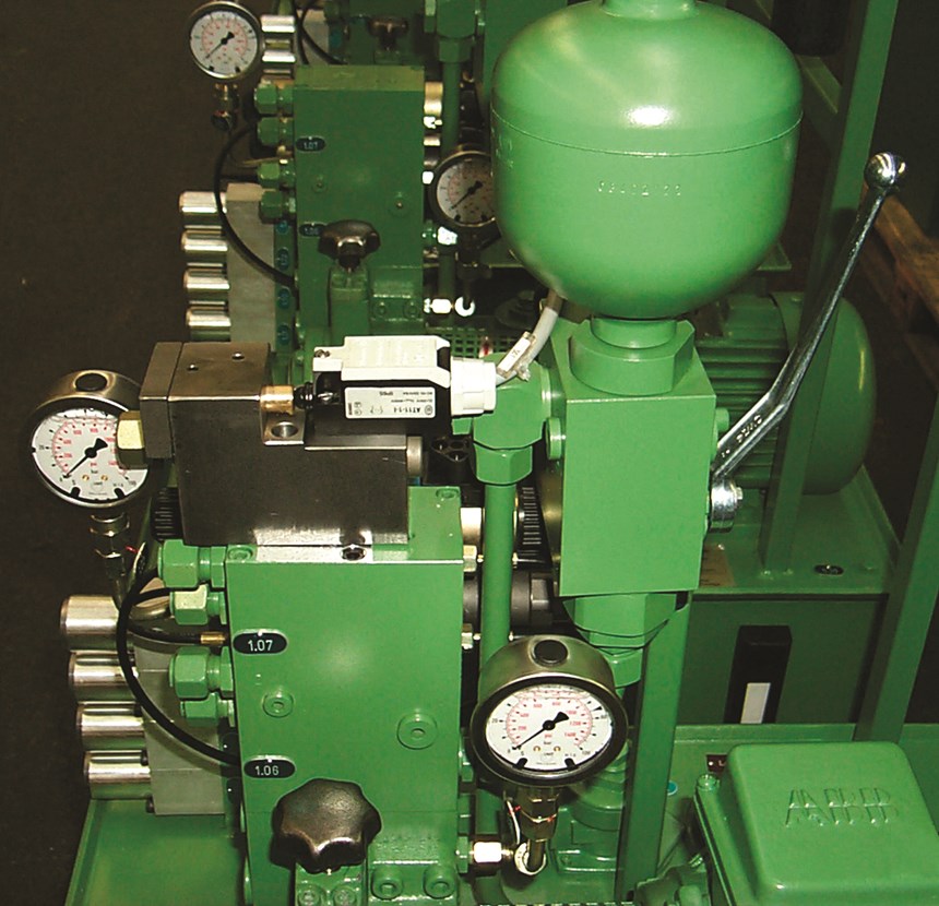
The hydraulic functions of the indexing chuck are controlled in a variety of ways, but the hydraulic control stand is most typical. With this mode of control, the chuck functions are switched via two solenoid valves. Four pressure switches are provided for monitoring the clamping and releasing function and the indexing positions. A feedback cylinder with normally closed contact indicates the indexing operation. The control stand is electrically pre-wired, and all signals are routed to a switch box and can be tapped off via a connector.
As the hydraulic fluid found all too frequently on plant floors attests, hydraulic lines can sometimes break. Along with the housekeeping headache this represents, it can also result in a loss of hydraulic force. That’s why as a safety function, the control stand is provided with a hydraulic accumulator. In the event of an interruption of the fluid supply, the hydraulic accumulator maintains the necessary clamping force to hold the workpiece securely in place until repairs are made and the system is up and running again. As an additional safety measure, the electrical circuit in today’s advanced indexing chucks includes an adjustable time-lag relay, which incorporates a short time delay between the indexing and locking cycles, ensuring that these operations are performed in the proper sequence.
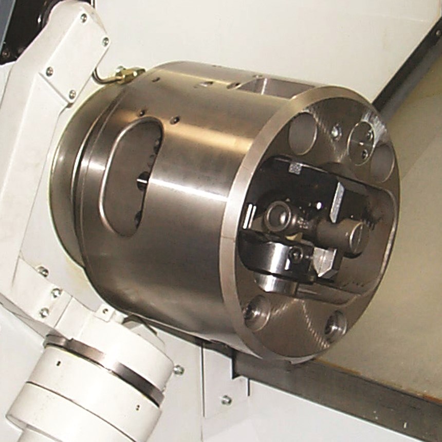
In a typical indexing chuck application, the chuck grips the workpiece with one clamping jaw and one indexing jaw. Hydraulic pressure behind the top or clamping jaw forces it toward the indexing jaw, thus gripping the workpiece. The design of the jaws and the gripping pressure create a centering effect that helps maintain the surfaces to be turned in the correct relationship with each other. As for the indexing mechanism, this employs two plungers and a multisided index spindle, all of which are hydraulically powered. The two plungers intersect the index spindle. The index plunger is actuated by an M-code command from the machine tool’s CNC, which then contracts the spindle, moving it through a portion of its indexing motion. At the end of its stroke, the index plunger retracts. Then the second plunger is actuated, moving the spindle through the rest of its motion.
Tight Grip
Devising chuck jaws for firm, safe gripping is one of the keys to successful turning, and this is especially the case in indexing chuck applications. Remember, these jaws need to be able to stand up to the forces generated by the cutting tools to be used and the clamping force generated by the chucking operation itself, along with the speed and feed rates. In addition, the geometry of the workpiece and any overhang should be considered; plus, the workpiece must be gripped in such a way as to ensure that all of the surfaces to be machined are correctly presented to the tool when they are indexed.
Universal joint spiders are highly illustrative in this respect. The machining of spiders has become one of the more common applications employing indexable chucks. This stems from the fact that today’s automakers and their major suppliers have largely discontinued the production of spiders on the high-volume special machines traditionally employed to machine these parts, switching instead to general purpose lathes equipped with automatic indexing chucks. The reason is that if the production of spiders is performed on one or a handful of high-volume special machines, then a breakdown of one machine can create a considerable production loss. If, on the other hand, the production is distributed to several general purpose lathes with lower production capacities, then the breakdown of one machine will not seriously hamper production. This also provides the plant with more flexibility, as it is possible to retool a lathe for other types of parts if the need arises.
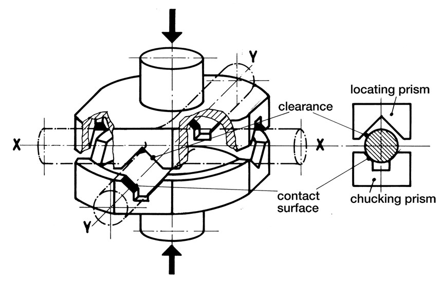
The preferred method for holding these parts in an indexing chuck uses the crossing prisms method. This employs two slightly variant V-grooves that form a cross. They are machined into a set of prisms that locate in the upper and lower chuck jaws. There are two of these V-grooves in the upper jaw, and two in the lower. One of the grooves has a clearance angle machined into it for locating the part. The second groove, machined to a tighter tolerance, performs the actual gripping. The prisms are offset 90 degrees. This ensures that a clamping V-groove is always opposite a clearance angle V-groove. This way, the spider is automatically seated in the prism, ready for the turning cycle. This crossing-prisms method helps maintain a secure hold on the part in the face of the forces introduced by the cutting tool. It also compensates for the dimensional fluctuations of the spider caused by the casting or forging process, helping to maintain the correct orientation of the spider’s four surfaces that require turning.
The Done in One Advantage
The ability to machine a part in one, as opposed to several setups, along with the ability to quickly change-over within a family of parts simply by changing chuck jaws, yields strategic benefits. Foremost is time. Eliminating multiple setups allows manufacturers to produce more parts in less time, increasing productivity and, thus, profitability.
This fact also opens up a variety of possibilities in terms of machine utilization. Freeing up machine time creates the possibility of bringing in more and different jobs, or, alternatively, of performing the needed work with fewer machine tools. It can also eliminate the need for the expensive special machines often used to turn and bore many of these parts. In addition, spreading the work done by a special machine over several flexible, general purpose turning machines ensures that production won’t come to a halt if a special machine goes down.
Sometimes overlooked is the part that quality plays in the indexable chuck equation. Location errors due to multiple chucking are eliminated. This benefit is magnified by the fact that the parts that lend themselves to this type of workholding are often cast parts. Cast parts typically have high and low spots on their surface, making it difficult to re-clamp the part on exactly the same area. Thus, each reclamping magnifies the possibility of error.
Indexing can generally be performed without stopping the spindle. This is a major benefit of indexing chucks, as it dramatically shortens the turning cycle and saves wear and tear on the machine tool because the spindle does not have to be stopped and restarted after each indexing.
However, as a general rule of thumb, it is preferable to peg the indexing speed at two-thirds the turning speed. This slight reduction guards against potential damage from unbalanced conditions that can occur with certain workpiece shapes.
The Right Speed
Is this the right speed for your indexing chuck application? The need for this precaution can best be determined empirically through a trial run in conjunction with a chuck supplier, with consideration for the degree of machining precision required and the desired surface finish, as well as any peculiarities in the geometry of the parts that need to be processed.
This highlights the fact that an indexing chuck is not something that one simply purchases from a catalog and slaps on to their turning machine. Installation is typically done by the chuck supplier and takes about 3 days. First, though, it is important to work with a chuck supplier to determine if an indexing chuck, as powerful a productivity tool as it is, is the best solution for a particular application and your specific business needs.
An increasing number of production facilities are asking those questions and answering with a firm “yes.” The resurgent auto industry is in this camp. The industry has seen the advantage of employing indexable chucks in the production of universal joint spiders. These advantages include faster production rates because of fewer setups; more flexibility made possible by the use of general purpose lathes, including the ability to quickly switch to new part families or, if the need arises, to switch production to another plant; and quality. Each time a part with crossing axes is unchucked and then re-fixtured the potential for error is increased. This is particularly so when dealing with cast or forged parts with their inherently variable surfaces, and parts with crossing axes are often forged or cast.
But these benefits are not limited to the auto industry. Smaller facilities are also taking another look at this workholding option. For many smaller firms battling to survive and prosper in today’s highly competitive and uncertain manufacturing environment, the cost saving potential of indexing chucks could well be a game changer.
RELATED CONTENT
-
When Thread Milling Makes Sense
Threading a workpiece is a fundamental metalworking process that every manufacturing engineer takes for granted.
-
Collets Vs. Chucks
Find the definition, types and advantages of both CNC collets and chucks for workholding as well as the best applications for each, in this article.
-
Turning to an Adhesive for Lathe Workholding
Adhesive cured by ultraviolet light is an option for securing parts for machining that could otherwise distort when traditional, mechanical clamping techniques are used.

