Pallet-Transfer Multi-Spindle Machining Center Defies Classification
Increasingly, new machine tools are being developed that defy existing classification code by virtue of their multi-tasking capabilities.
Watch here for an animation of the Icon machine in action.
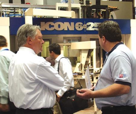
A new machine tool concept was introduced to the public for the first time at IMTS 2008, garnering much interest and more than a few quizzical looks. For many of those passing by and getting a first glimpse of this new machine, their first response was to cock their head to the side slightly and wrinkle their brow. You could see the wheels turning as they tried to put the Icon 6-250 into one of the standard machine tool categories. Is it a horizontal machining center? A vertical? Or is it a rotary transfer machine? Maybe it’s an FMS? Actually, this new machine concept may well require its own “all of the above” category.
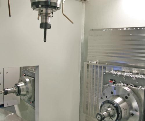
The Icon concept neatly packages four machining positions around a six-pallet table, bringing together the efficiencies of rotary transfer production philosophy with a machining center attitude. It is designed to address the issue of time wasted between machining centers on traditional FMS transfer methods by employing a pallet transfer table. It’s just one method used to speed the process. Also, by spreading the work over four stations and as many as eight spindles at once, the cycle time for a finished part is cut substantially while enabling five-sided workpiece machining with single clamping accuracy.
Featured Content
Why The Icon?
According to Hydromat’s president and CEO, Bruno Schmitter, “The idea for the Icon was conceived about 2 years ago. I looked at the marketplace for a productive and flexible multi-spindle machining center, and when I could not find any viable offerings, I decided to build the Icon to fill that void in the market.”
Icon Technologies, a new division within Hydromat, was formed to focus on offering a new twist on the rotary transfer concept with the Icon 6-250 flexible machining center. But don’t mistake this machine for a highly dedicated, inflexible transfer line.
“The design intent for this machine is to provide a multi-spindle, horizontal and vertical machining center based on proven concepts and components,” Mr. Schmitter explains. “Except for tooling, in most cases the machine’s flexible design does not need to be re-configured for each machining application.” Further, flexibility comes from the use of Fanuc standard programming, standard tooling, and fixturing that is typical of any horizontal machining center.
“The niche for the Icon is production work from 500 pieces-plus in all manufacturing segments,” Mr. Schmitter says. The machine represents an effort to provide a viable entry into the area of precision production equipment for discrete part production runs in ranges from a 2-inch to a 10-inch cube.
The 6-250 section of the name refers to the six-position pallet transfer table, and the 250-mm (10-inch) cube work envelope. Is the concept scalable? “Conceivably there could be a larger and a smaller machine than the 6-250, but the market need will determine that,” Mr. Schmitter answers. After the Icon had its debut at IMTS he was happy with the crowd’s reaction. “The machine was very well received at the show, and some concrete inquiries developed. We are very pleased with its debut.
A Compact, Solid Base
During Hydromat’s initial market research to determine the needs of its customers, several issues seemed to be universal. One of these was floor space and the need to use each square foot well, helping to keep overhead down. Mr. Schmitter formed a staff to put his vision into action. “An engineering team was created who looked at various solutions to accomplish the requirements and specifications,” he says. The new design team was tasked with creating a plan that left little, or no, wasted floor space. The result is a design that can open up areas that otherwise would be gobbled up by a multi-machine system.
The four machining stations are enveloped by a self-supporting machine base and frame weldment constructed of 50-mm thick steel plates that some may describe as ‘overkill.’ “The machine frame is a solid weldment engineered and optimized with finite element analysis software to provide an accurate and solid structure for the machining units,” Mr. Schmitter explains. “Therefore, it is possible to conduct roughing and finishing operations simultaneously in isolation without concern for transferring vibrations from one station to another.”
Space Saver
The productivity upside of engaging four horizontal machining spindles and two to four vertical machining spindles simultaneously on a part, and to do it on a single platform in the same floor space of roughly two horizontal machining centers, is something to consider. That’s effectively six to eight machining centers working in the same space as two. For shops doing production work on horizontal machining centers, especially when machining four- or six-sided parts, this machine tool concept represents a paradigm shift in productivity potential and floorspace requirements.
The marketplace has been resourceful combining single-spindle machining centers with various forms of automation, but maintaining global competitiveness with higher production output demands that shops minimize non-cutting time and multiple presentations to the machine, such as re-chucking and A/B loads. This machine delivers on these critical criteria while applying the efficiency of rotary transfer.
“If a shop is running production parts on a standard single-spindle FMS, the Icon technology can vastly improve productivity and take up significantly less floor space,” stated Jim Otten, vice president of sales for Hydromat Inc. and Icon Technologies. “The benefits of FMS technology can be dragged down by slow pallet movement and the use of a large amount of real estate. One might think about this in terms of throughput per square foot.”
Full B-Axis Interpolation
Each of the four machining stations on the Icon is equipped with a Swiss-made Lehmann index drive for B-axis motion. These drives have an indexing accuracy of ±4 seconds (0.001 degree) and an index speed of 1.8 seconds for a 180-degree turn.
The integrated control pivot includes three hydraulic clamp circuits, one hydraulic return and one airburst for chip expulsion. Full fourth-axis interpolation is possible on all stations with this system.
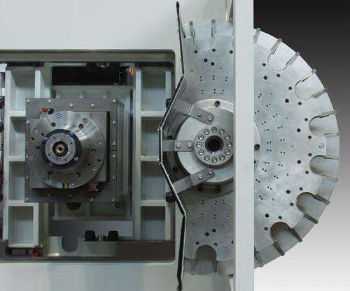
A Schunk two-part pallet system is mounted on top of the Lehmann index drives. A mounting and clamping module is affixed to each B-axis drive as well as each of the two loading stations for a total of six pallets. A heavy-duty integrated electromechanical pallet-changing table moves all six pallets and their workpieces to their next station. When in position, the table lowers the centering sleeve of each pallet onto the mounting and clamping module.
A hydraulically actuated locking system activates while a back pressure monitoring system takes a reading from air jets, determining proper seating of the pallet. An air purge keeps the locating surfaces clean while a turbo function significantly increases the pull-in force. This sophisticated system ensures a high level of repeatability. The Schunk pallet surface measures 300 mm across and features a universal bolt pattern for standardized workholding. Each pallet can accept a load of as much as 140 pounds.
As Many As Eight Tools Cutting At Once
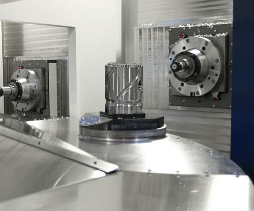
The Icon 6-250 is equipped with German made Kessler water-cooled integrated spindle motorswith a bearing size of 70 mm and rated at 45 horsepower. In 1 second they are able to accelerate to 12,000 rpm. Each spindle is ready to cut material at all four machining positions simultaneously.
The spindles are housed within square rams with the machining unit’s axis movements riding on linear guides powered by Fanuc servomotors, which drive pre-tensioned ballscrews. Ballscrews for the X and Z axes feature 40-mm × 10-mm pitch units, and the Y axis employs a 50-mm x 20-mm pitch ballscrew.
With four horizontal and as many as four vertical three-axis machining modules, the Icon methodology can introduce as many as eight tools in the cut on four workpieces at once. All four machining stations offer five-sided machining with full fourth-axis interpolation.
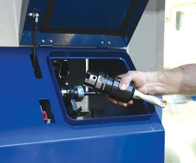
The stroke on the X and Y axis is 300 mm, while the Z axis extends to 360 mm. The X and Z axes apply a machining force of 16.2 foot-pounds (22 Nm) of force, while the Y axis is rated at 22.1 foot-pounds (30 Nm). Each machining station has its own access door with a window for easy access to the tool spindles.
Standard spindle motors are 12,000-rpm units that produce 74 foot-pounds (98 Nm) of torque at 3,500 rpm, and 21 foot-pounds (29 Nm) at the top end. Spindle units can also be equipped with optional 8,000- and 24,000-rpm spindles, depending on the needs of a particular
application.
Each machining module is equipped with its own ten-position toolchanger. On a fully equipped, eight-spindle machine, that’s as many as 80 tools available at a moment’s notice. The toolchangers and spindles use a HSK63 toolholding system as standard.
The maximum tool weight is 15 lbs with the maximum tool length and diameter being 250 and 125 mm, respectively. Aided by use of a direct pickoff method rather than a tool arm, chip to chip time is 2.8 seconds.
Loading And Gaging Stations
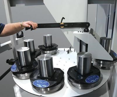
For moving workpieces from station to station, a six-pallet rotary table is used. Since the machine has four machining stations, two of the pallets are presented to the loading stations with each index.
The Icon’s loading station is designed for manual or robotic production configurations. Several means of loading the component parts into the machines are available. An economical alternative to robot loading was displayed at IMTS. It is a simple pneumatic-assisted semi-automatic loading device that showed how an operator could easily unload and reload the heavy pallets without physical strain.
The Icon has a large primary door that provides easy access to the loading station. This area is completely sealed off from chips and coolant by an interior steel safety door. On the operators command, the polycarbonate outer door closes, the safety door rises, and the cam-controlled electromechanical pallet changer lifts, rotates and places all six pallets at their next stations in only 4.5 seconds.
While the completed part is extracted and the next workpiece is readied for the cutting process, all four machining positions continue to produce parts, keeping the machine in production and improving productivity. At the fourth position an identical loading station to the first is available for re-clamping or gaging processes. It also serves as a secondary loading station for double production processes.
Double Production
With all those spindles available, on selected applications the Icon can be set up to do double production, increasing efficiency even further. In one scenario, the table can be indexed two positions to produce two parts with each cycle rather than one. Another setup could yield two different parts.
“If a shop is currently running production on horizontal machining centers, especially in cases with multiple presentations, like an A/B load between two or more horizontal machining centers, the Icon is must-see technology,” Otten concludes. “It could put those companies in an enviable competitive position to land big impact programs for their companies.”
Two Pendants, No Waiting
The Icon 6-250 comes equipped with a Fanuc 30i, which is more popular in the North American marketplace, or the Siemens 840d control, favored in the European marketplace. The machine features dual pendants for operation from both sides of the machine. Once a machinist begins work on one side of the machine, the other pendant is locked out for safety reasons.
Keep It Clean, Keep It Cool
One striking feature on the Icon is its coolant and filtration system. Mr. Schmitter’s initial market research concluded that undersized coolant systems were a source of some issues for those shops doing quantity jobs. The new machine was designed with production runs in mind. That’s why it’s equipped with a
1,200-gallon Knoll coolant system to aid in keeping coolant troubles at bay. This system supplies the working zones with plenty of fluid to keep each machining area free from the accumulation of chips, as well as keeping temperatures regulated.
A vacuum filtration drum provides clean water-soluble coolant for medium pressure (30 bar/435 psi) at the spindle for through-the-tooling coolant. Optional high-pressure (80 bar/1160 psi) coolant supply for deep drilling operations can be connected upon demand. A self-cleaning filtration system with a vacuum is standard, as well as dual scraper-type chip conveyors.
U.S.-Based Engineering And Service
Icon project engineers based in St. Louis will be working hand-in-hand with customers to develop unique, tailored manufacturing process solutions. An engineering committee, including an array of manufacturing disciplines, monitors every phase of each project.
The Icon concept was developed as a response to industry needs. Mr. Schmitter is confident that his machine will fill a particular gap. “The market has helped itself with single-spindle stand-alone solutions, but in many cases, a higher production throughput is required to be competitive in the world market. We believe the Icon is able to deliver this need,” he concludes.
RELATED CONTENT
-
Shop Continually Improves by Adopting Rotary Transfer Machines
American Turned Products’ founder left a legacy of continuous improvement, helping the company grow as it implemented rotary transfer machines and preparing it to take on new work.
-
Rotary Transfer Offers Full OD Turning Between Centers
This small-footprint trunnion rotary transfer machine includes an isolated cell to perform full OD turning between centers for improved concentricity compared to flipping parts in a station for backside turning or moving the part to another clamping position.
-
Rotary Transfer Versus Swiss for Small Precision Parts
A little creativity goes a long way in meeting the challenges that this high-production application presents.


