Cutting Tool Coating Production
This article looks at the coating methods available for carbide cutting tools.
#basics
There are five primary reasons for using coating tools: to increase wear resistance; to increase oxidation resistance; to reduce friction; to increase resistance to metal fatigue; and to increase resistance to thermal shock.
When cutting tools are properly coated and perform as designed, the result for the end user is higher cutting data, longer tool life and the possibility of dry machining.
Featured Content
Methods for Coating Cutting Tools
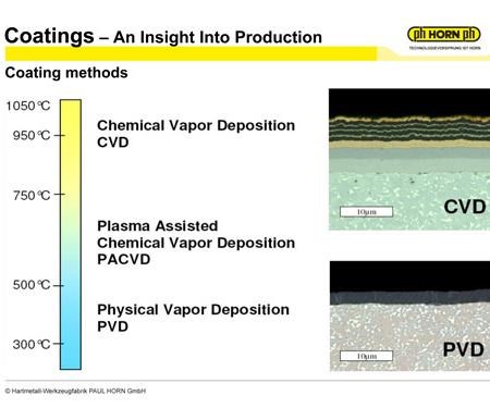
There are two primary processes in place for coating cutting tools: CVD (Chemical Vapor Deposition) and PVD (Physical Vapor Deposition). Each of the methods has its own advantages and disadvantages.
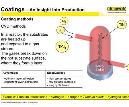
CVD coating was the original and most commonly used coating method for many years. The CVD method involves heating up the substrate within a chemical reactor and exposing the substrate to a gas stream. The gases break down on the hot substrate surface, forming a coating layer. In general, the CVD method requires temperatures around 1,000 degrees C.
A common coating uses the three gases TiCL4 (titanium tetrachloride), H2 (hydrogen), and N2 (nitrogen) to produce TiN (titanium nitride) + HCl (Hydrogen Chloride). The HCl is a bi-product of the process and must be disposed of according to strict environmental regulations.
The advantages of the CVD method include optimal layer adhesion, as well as consistent layer distribution. The disadvantages of the CVD method are high temperatures affecting the substrate, few suitable materials for coating as the coating material is fed in a gaseous form, and long cycle times.
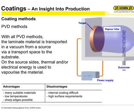
PVD coating is the newer of the tool coating methods and is becoming increasingly popular in the industry. The PVD method involves transporting laminate material in a vacuum from a source via a transport space to the substrate. The laminate material is vaporized using either thermal or electrical energy from the power source, which then allows the vaporized material to adhere to the substrate.
The advantage of the PVD process is the range of suitable materials for coating, relatively low-operating temperatures, around 450° C, allowing for coating of sharp cutting edges. The disadvantages are that coating of internal surfaces is difficult (coating requires a line of sight from the laminate material to the substrate) and the surface requirements of the substrate are much higher.
Primary Coating Methods
With PVD, there are two primary technologies used to coat the different substrates: the arc method (arc discharge) and the sputtering method (cathodic sputtering). Both methods share one additional advantage; the coating chambers are relatively easy to construct.
The arc method involves an electrical power source (much like a lightning bolt) hitting the laminate material and transforming this material from a solid to a liquid to a gaseous phase.
The arc method involves an electrical power source (much like a lightning bolt) hitting the laminate material and transforming this material from a solid to a liquid to a gaseous phase. The advantage of this process is high layer rates (in relation to sputtering). However, since the laminate material is in all three phases (solid, liquid and gas) the potential for droplets (minute liquid particles) occurs. These droplets do not achieve the gaseous state.
The sputtering method involves a thermal energy source, which transforms the solid laminate immediately to a gaseous state. No droplets occur as the material skips the liquid phase. However, the lower layer rates (in relation to arc), results in longer cycle times.
Hard Material Coatings
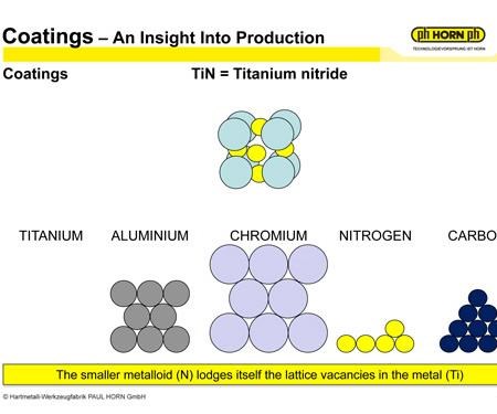
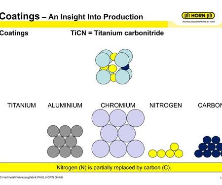
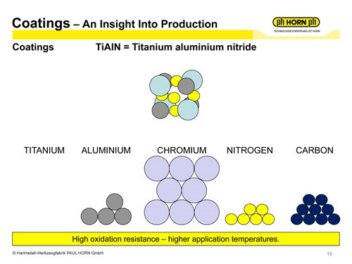
Most hard materials (coating is a hard material) consist of a metal and a metalloid. Some examples of cutting tool’s familiar coatings are TiN (titanium nitride), TiCN (titanium carbo nitride), TiAlN (titanium aluminum nitride), AlTiN (aluminum titanium nitride) and AlCrN (aluminum chromium nitride). The periodic table of elements shows the inventory of metals and the metalloids that are potential candidates for coatings.
During the coating process, the smaller metalloid—in the case of TiN, the nitrogen or N—lodges itself in the lattice vacancies of the metal titanium (Ti). When switching to TiCN, the carbon (C) partially replaces some of the nitrogen (N). Following the same logic, the metals and metalloids required for the other sample coatings can be determined.
This is one of the advantages of the PVD process. Since the metal is solid in the PVD chamber (CVD introduces in a gaseous phase), almost any metal is usable for coating. Of course, not all metals are beneficial, but they are available for use.
Coating Layer Structures
Through the years of development coating, layer structures have undergone many changes and improvements. There are generally five different layer structures in coating technology.
The monolayer structure, as the name suggests, is only one layer of coating. While looking at the structure under a microscope, tall columns of coating are visible. This is easy to apply, but it also is easy to crack and damage. Imagine a ball hitting a bunch of columns. The columns will start to fall down, and the crack will easily penetrate all the way to the substrate.
The multilayer structure is many different monolayer structures on top of each other. Damascene steel is a historical example of this type of structure that combines the properties of several materials to make a surface that is both tough and hard.
Nanolayer structures are the same as multilayer, but substantially smaller; the layers are at the atomic level of thickness.
Nanocomposite coatings use similar technology as carbide cutting tools. The nano structure combines the toughness of the binder phase (cobalt as an example with carbide) with the hardness of the nanocomposite coating.
The gradient structure gets its capabilities by starting out soft and elastic at its core, and then near the surface it becomes hard and wear resistant.
Quality Control and Inspection of Coatings
After coating the cutting tools, as required in every step of the manufacturing process, the manufacturer needs to perform a quality inspection on the coatings themselves. The quality inspection process and procedure normally involves four areas of inspection layer thickness, layer adhesion, layer construction and structure, and layer composition and distribution.
Inspecting layer thickness. There are two primary methods for doing this: checking by Calotte grinding or using X-ray florescent radiation.
Calotte grinding involves using a small diamond grinding wheel (ball) that grinds away the coating to reveal the substrate below.
Calotte grinding involves using a small diamond grinding wheel (ball) that grinds away the coating to reveal the substrate below. Then, by viewing the ground away area by a microscope, the layer thickness can be measured using the formula (XxY)/ball diameter. Where X is the coating width from a top view, and Y is the substrate plus the coating width from a top view. The goal is to have the achieved value with the coating thickness range the manufacturer specifies.
X-ray florescent radiation can be a more accurate methodology as both the coating and the substrate material produce X-ray fluorescence radiation, but the coating weakens the substrate’s radiation. The degree of weakness of the substrate’s radiation is measured by the secondary emissions and therefore, determining the coating thickness. A preferred method is Calotte grinding, as it is easier to see, feel and touch.
Layer adhesion. Once the layer thickness is in tolerance, the next check is layer adhesion. This is probably the most subjective of the quality control tests. Rockwell indentation, and the scratch test are the two methods for checking layer adhesion.
Rockwell indentation involves exactly what it sounds. A hardened ball is pulled down onto the coated substrate at a set force. The coated substrate cracks, and the inspectors review the cracks at the indentation point via a microscope and evaluate the number and intensity of the cracks. Dependent upon the individual criteria set forth by the manufacturer, the inspector determines if it is acceptable or if it fails inspection. While this seems straightforward, the coating thickness also affects the number and intensity of the cracks, so a thicker coating would allow more cracks than a thinner coating.
The scratch test is a bit more direct. In the scratch test, the inspector places an indenting tool under an increasingly progressive load across the cutting tool. At the critical load Lc, the coating starts to crack. At this point, the distance traveled is measured, and if far enough, the adhesion is acceptable.
Layer construction and structure. With the thickness good and the adhesion acceptable, the next step is to review the layer construction and structure. This is reviewed in the same manner as the layer thickness by calotte grinding. Using the same ball, the coating ground away and viewed under a microscope. Here is where the different layer structures mentioned above are visible and can be confirmed.
Layer composition and distribution. The last quality control check is the layer composition and distribution. This requires a scanning electron microscope and energy dispersive X-ray technology (SEM/EDX). The SEM produces extremely high magnification of images (as much as 200,000×) at high resolution combined with the EDX analysis to determine the materials and amounts of material in a small section of material (as small as 2 nanometers).
In-House vs. External Coating
The last portion of an insight into the production of cutting tool coatings is where the coating takes place. There are tremendous advantages of coating the tool in house versus using an outside source; however, coating in-house does require a substantial capital investment.
The advantages of in-house coatings are logistics, processing time and quality.
Logistically, a manufacturer does not have to package a product for coating nor is shipping required. This will usually save a minimum of two working days. Not only is there a reduction in processing time, but there’s the added advantage of being able to react to bottlenecks in production and provide less than 24-hour door-to-door time.
Another advantage is in the quality of the coating. Manufacturers performing coating operations in house have the ability to use product-specific racking and pretreatment. They have the ability to ensure there are homogenous batches with no product mix. Therefore, tolerances can be reduced when coating a product in-house.
An outside coating source may have multiple types of products within a coating furnace, and they may have a total tolerance band of 2 to 4 microns for the coating. In-house coating, with homogenous batches, would allow a tolerance band of ± 20 percent from a nominal size. If 2 microns were nominal, the coating would have a total tolerance of 0.8 micron (versus 2 microns). The layer thickness distribution resembles a bell curve, so 81 percent of the product would have a total tolerance of 0.4 micron.
There is a lot of time, energy, science and thought that enters into the coating of a cutting tool. A cutting tool manufacturer’s goal is to provide a product to help the user produce their parts faster and more accurately.
Hopefully, this helps provide some insight into the coating production process and serves as a reminder that there is some serious technology behind that pretty gold insert.
For additional information on this topic, read “A Guide to Insert Coating Processes and Materials.”
RELATED CONTENT
-
Calculating Surface Footage and RPM for Optimum Tool Life
Tech Brief: Calculating Surface Footage and RPM for Optimum Tool Life
-
Skiving Long, Slender Parts with Tight Tolerances
Here's a look at one of the oldest and most efficient methods of screw machine production for parts that are long and slender, with close-diameter tolerances and finishes, or parts that require truly spherical radii.
-
Tools and Technologies for Deep Hole Drilling
Understanding the challenges of deep hole drilling and knowing how to select and apply the appropriate tools will help a shop profit from this operation.


